Define measurement requests during data entry
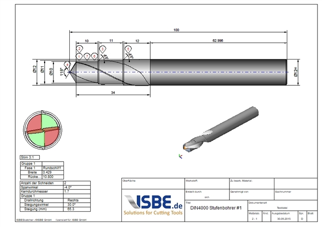
Semi-standard or special tools are manufactured on the basis of special requirements. The most important features are known when creating data and drawings. Why not define the measuring instructions right away and make them available for the measuring machine and the test protocol? This saves time and unnecessary questions are a thing of the past. All measuring points with corresponding tolerance are always available.
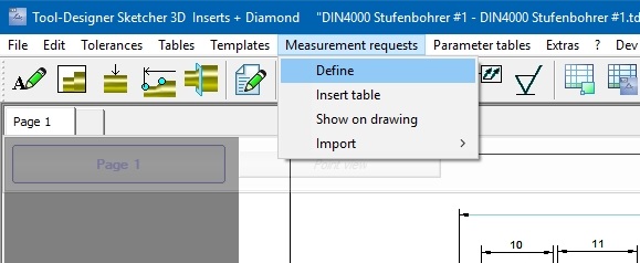
Once the data has been defined in the TD Sketcher and the drawing has been generated, you can define relevant dimensions using the 'Measurement requests'. Choose the measurement type from the left column and enter the necessary parameters in the right area. The snap points are used for quick selection of the measurement location. However, this can be set individually by specifying 'Position X1'.
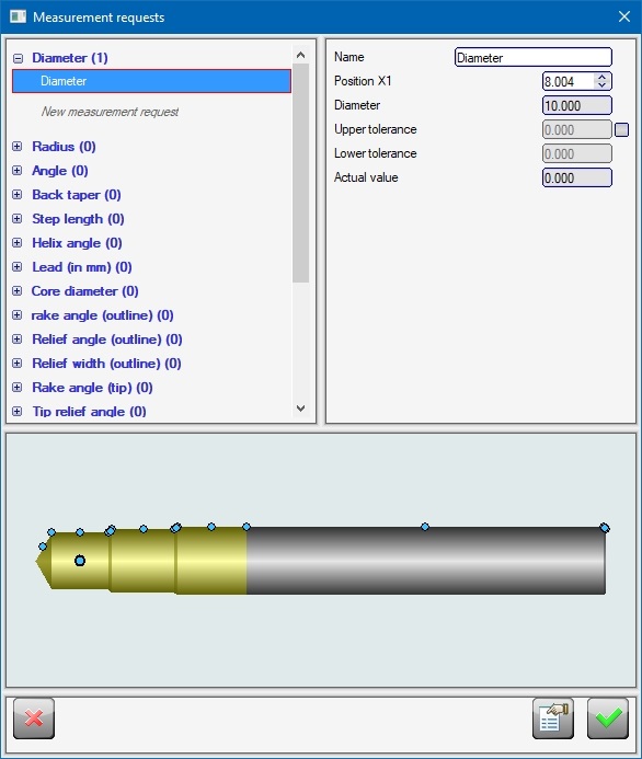
Any number of measurements can be defined for each measurement type. Via the context menu of the measurement in the left area, a defined measurement can be activated or deactivated. This avoids the need to delete measurements if they are to be used later.
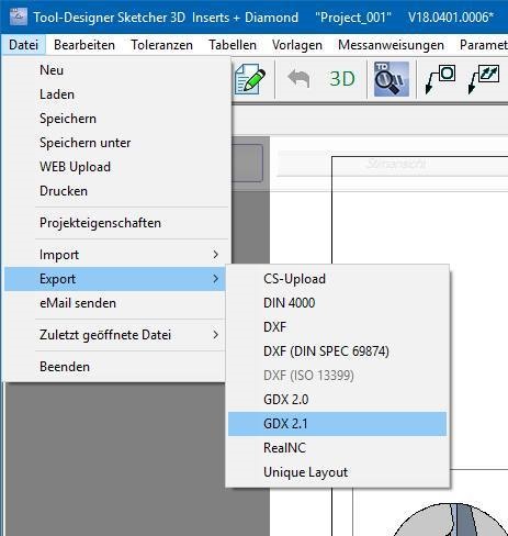
The export of the measuring instructions, e.g. for the measuring machine, is done via the menu 'File'/'Export'/'GDX 2.1'. The GDX 2.1 file can be read by the measuring machine and execute the measuring instructions. Once measurement instructions have been defined, they are automatically added to the TD Sketcher project file and are therefore available at any time.
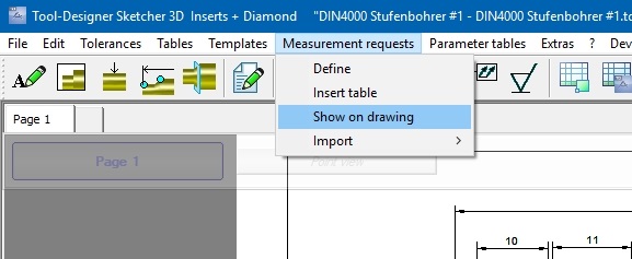
The measuring points can also be shown on the drawing. The measurement points are displayed as indexes via the menu item 'Measurement instructions'/'Show on drawing'. It is also possible to add the measurements as a table to the drawing.