Derive blank geometries from tool data with just a few clicks
When it comes to the manufacturing of the tool after its drawing is completed, often an drawing or sketch for the preparation of the blanks must be created additionally. It's obvious that a blank should be easy derived from the existing tool data. Another advantage: A new drawing doesn't have to be sketched again in case of a upcoming change.
The Data Interface describes the Geometry Information of the Cutting Tool, the associated Grinding Wheel, its positions and Wheel Paths. The top-down principle can be applied when developing Cutting Tools, which offers Advantages for the User.
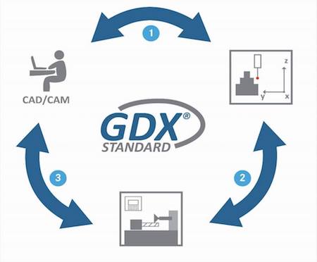
A GDX file can be created in the CAD / CAM System used by the User to import the Geometry Information into the Tool Grinding Machine or Measuring Machine. The Tool can now be manufactured using the imported Tool Geometry Information.
Ground Tools are inspected by the Measuring Machine alternatively, to have the Deviations from the Nominal Values determined. If the result is positive, a QA Protocol is written, otherwise the Tool must be ground again. In this case, the GDX file can be used again.
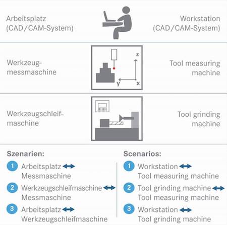
Due to the GDX Uniform Data Structure, Programming Software, Grinding Machines and Measuring Machines interact in a uniqe way. The universal use of XML is used to enable the standard of exchanging data between different applications.
The User can choose between Machines from different Manufacturers, since there is a Standardized Exchange of Data between them.
For more information visit www.gdx-online.de