Add coolant holes and adjust them perfectly
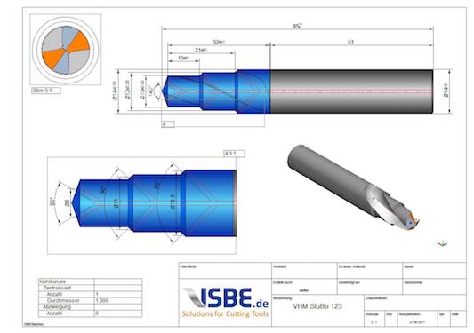
The correct design of the coolant holes is an enormously important detail in every quotation and production drawing. The outlets should hit the cutting edge at which the coolant is most effective. However, in the definition, care must be taken to ensure that the holes do not lead to undesired breakthroughs, e.g. in the groove. It is therefore important to know in which position the outlets have to be turned to the cutting edge.
The TD Sketcher offers an easy-to-use interface for the definition and design of the cooling holes. In the tool assistant, both spiralized cooling channels, as commonly used in the blanks or a central coolant hole with up to three radial outlets can be arranged in the tool.
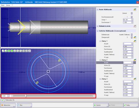
An exact cut plane is formed to make the eases easier to locate by using the slider at the bottom of the screen. The A-position allows accurate positioning to the cutting edge and prevents an undesirable breakthrough in a non-intended location. In addition, the outlet angle and the pitch circle of the outlets or the position along the tool axis can be specified.
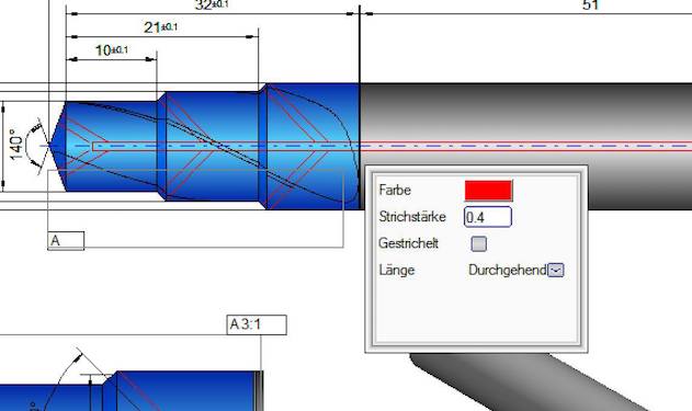
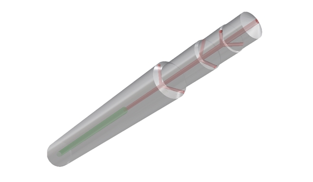
Using the properties in the context menu, the color, display and line thickness and type are set for the drawing view. This is how the cooling holes can be accentuated in the tool drawing. In addition, the cooling holes can be dimensioned and displayed in a further view for more detail. The cooling holes are also displayed and provide immediate information about possible breakthroughs in the optional 3D simulation.