Highlight permitted deviations by geometric tolerances
Shape and position deviations to the ideal geometry are caused by various factors during the manufacturing of tools. The full function of the tool can not be guaranteed and impairments occur even by setting dimensional tolerances. Geometric tolerances describe additional deviations, which cannot be determined by pure measurements at specific positions. Additional information on geometric tolerances thus minimizes the risk of a reject.
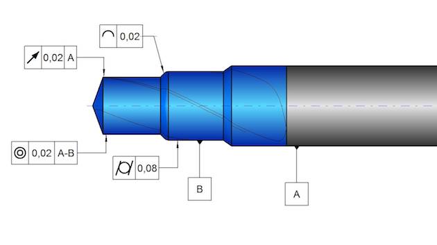
The most important and used geometric tolerances can already be defined in the TD Sketcher during drawing creation. Thus, the necessary characteristics for functional suitability of the tool are already established and documented.
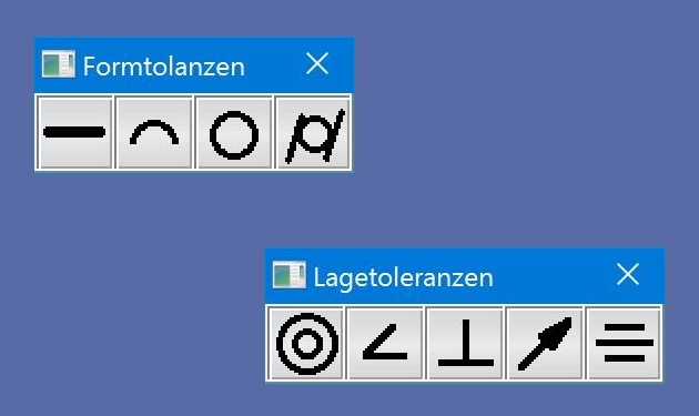
The geometric tolerances can be opened directly via the toolbar or via the menu 'Tolerances'. The small pallets help to select the desired tolerance. Depending on the selected tolerance, the complete symbol is attached to the mouse pointer and can easily positioned on the element which is to be tolerated. Possible reference datum are also attached after positioning the tolerance in order to position them one after the other.
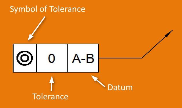
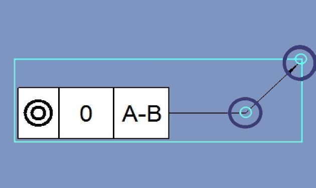
The tolerance or the datum can be opened by double-clicking in the respective field for editing. The reference arrows can also be changed in position. Move the mouse pointer to the top of the arrow until a small circle appears. Now you can change the position of the arrow by clicking. It is also possible to change the position of the break point in the reference arrow.